MINI R56 Crankshaft Sensor: Scope Test Before You Replace It
Quick Summary
A crankshaft position sensor is one of the easiest parts to sell on an R56 that cranks and will not start, and one of the easiest to sell unnecessarily. This write-up is the test sequence used on a 2010 MINI Cooper S with an N14 engine: read the wiring diagram, inspect the connector, verify supply and ground, prove the Hall element switches with the sensor in your hand, then scope the crank and cam signals together while cranking. On this car every one of those steps passed — both sensors switched cleanly and the crank pattern measured 364.5 Hz — but the signal amplitude came in at 2.6 V peak to peak instead of roughly 5 V, on both sensor circuits at once, with correct supply and ground at each connector. Because the high level on these circuits is supplied by a pull-up inside the DME and only switched to ground by the sensor, low amplitude on two circuits simultaneously is a module finding, not a sensor finding. No sensor was condemned on the strength of the waveform alone.
- Vehicle
- 2010 MINI Cooper S (R56, N14 1.6L Turbo)
- Difficulty
- ★★★☆☆
- Repair Time
- 1 hours
- Outcome
- Crankshaft and camshaft sensors proven to be switching correctly on the scope, low signal amplitude traced to the DME rather than to the sensors, no sensor sold on the strength of a guess
Fault Codes
Vehicle Information
| Year | 2010 |
|---|---|
| Model | Cooper S |
| Chassis | R56 |
| Engine | N14 1.6L Turbo |
| Transmission | 6-speed manual |
Repair Timeline
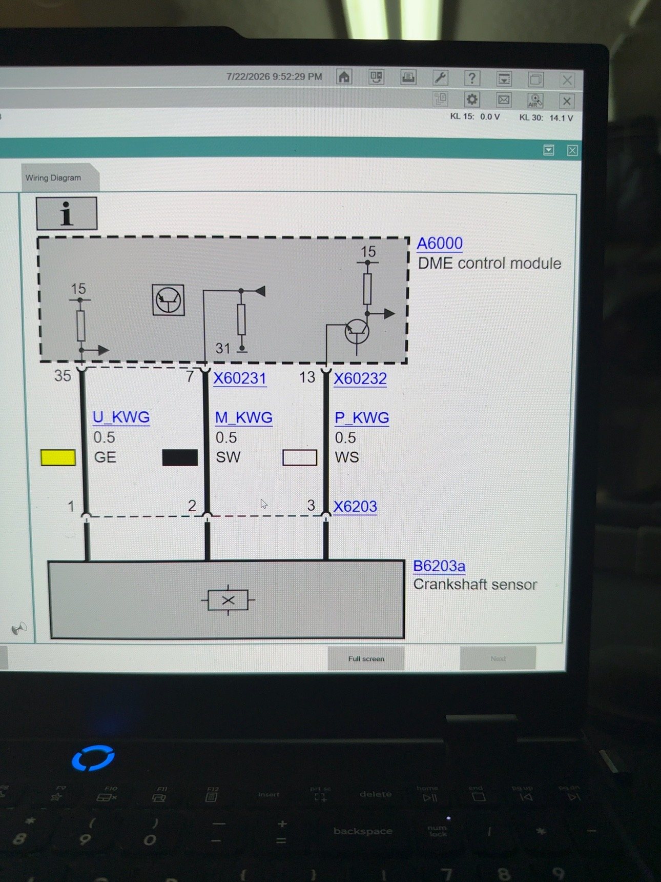
- Step 1 Diagnosis Wiring diagram pulled in ISTA. Crankshaft sensor confirmed as a three wire Hall-effect sensor - pin 1 supply (U_KWG), pin 2 ground (M_KWG), pin 3 signal (P_KWG).
- Step 2 Diagnosis Connector inspected for oil contamination, bent terminals and previous repairs before any meter or scope lead was attached.
- Step 3 Diagnosis Supply and ground verified at the sensor connector with the key on, then the signal line scoped against sensor ground.
- Step 4 Diagnosis Sensor removed from the block but left plugged in. A steel wrench passed across the tip pulled the signal line low and released it high, proving the Hall element switches.
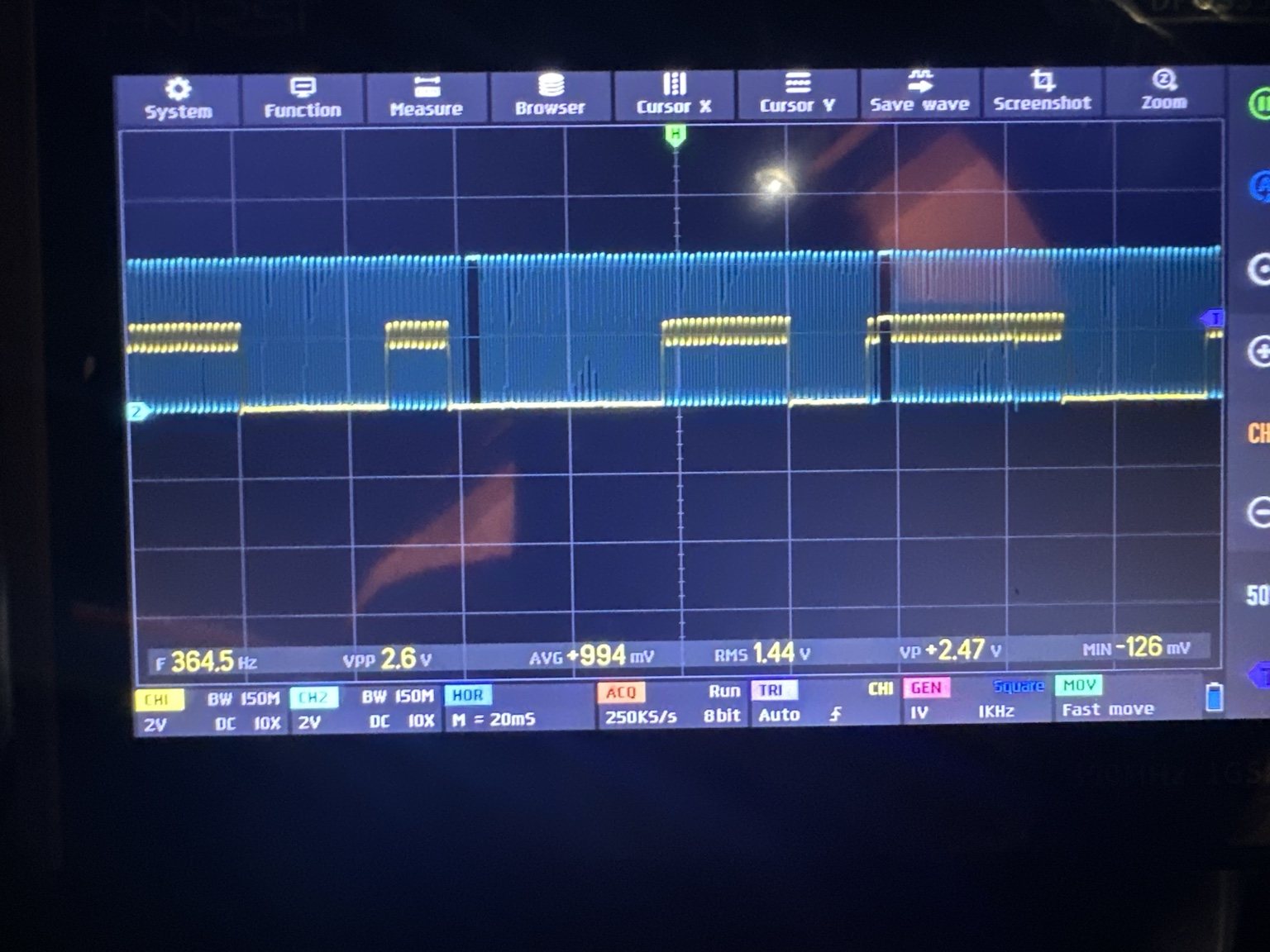
- Step 5 Diagnosis Crank and cam signals captured together while cranking. Both switch cleanly, 364.5 Hz on the crank pattern, but amplitude is only 2.6 V peak to peak instead of roughly 5 V.
- Step 6 Verification Low amplitude present on both sensor circuits at once, with correct supply and ground at each connector, points at the shared pull-up inside the DME rather than at either sensor.
Customer Complaint
The vehicle cranked at normal speed and would not start, with no engine RPM reported by the scan tool while cranking. That symptom is what puts the crankshaft position sensor circuit at the top of the list, and it is also what makes it tempting to fit a sensor before testing one.
Symptoms
- Engine cranks at normal speed but does not fire
- No engine RPM reported while cranking
- Crankshaft position sensor circuit implicated by fault code P0335
- Crank and cam signal amplitude low on the scope at roughly half the expected level
- Signal pattern itself clean, with no missing pulses or noise on either channel
Diagnostic Process
Read the wiring diagram before touching the connector. The R56 crankshaft position sensor is
a three-wire Hall-effect sensor. In ISTA the circuits appear as pin 1 U_KWG (supply, yellow,
0.5 mm²) to DME pin 35, pin 2 M_KWG (sensor ground, black) through connector X60231 pin 7, and
pin 3 P_KWG (signal, white) through connector X60232 pin 13. Knowing which wire is which before
back-probing matters, because two of the three tests below are meaningless if the reference lead
is on the wrong pin.
Note what the diagram tells you about the signal line. The DME side of the signal circuit is drawn as a resistor from the module's internal supply down to the input, with a transistor to ground. That is the shape of a pull-up: the DME holds the signal line high and the sensor's job is to pull it low. Nothing in the sensor generates the high level. This single detail is what makes low amplitude interpretable later.
Inspect the connector. Before any test equipment goes on: broken locking tab, bent or spread terminals, corrosion, moisture, oil contamination, chafed wiring and evidence of previous repairs. Oil wicking up the harness into this connector is common on these engines and has to be corrected before the electrical results mean anything.
Verify supply and ground at the sensor, not at the module. Channel 1 goes on the supply wire referenced to the sensor's own ground pin. Measuring supply against chassis ground instead hides a bad sensor ground, which is exactly the fault a technician most wants to find. The reading should be steady with the key on and should stay steady through cranking; a voltage that collapses while cranking is a wiring, connection or module supply problem, not a sensor problem.
Bench test the Hall element without cranking. Unbolt the sensor from the block, leave it plugged in, ignition on, scope still on the signal line. The line should sit high. Pass a steel wrench across the sensing tip and it should snap to near zero, then return high as the metal leaves. That is the whole sensor tested — power, ground, Hall element and signal path — in a few seconds, without a starter motor and without removing any doubt about air gap or reluctor condition yet. On this car the sensor did exactly that.
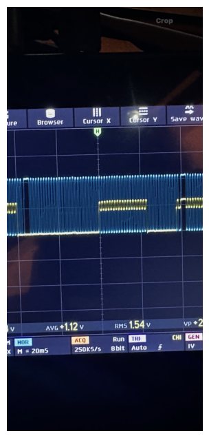
Capture crank and cam together while cranking. Channel 2 on the crank signal, channel 1 on the camshaft signal, both referenced to sensor ground, 2 V/div, 20 ms/div. Both traces switched cleanly. The crank pattern measured 364.5 Hz, which is the right order of magnitude for cranking speed on a 58-tooth wheel, and the reference gaps repeated at a consistent interval. The camshaft trace showed its longer, slower blocks with the crank pattern running underneath — the pattern you want to see, and it is worth capturing both channels at once rather than one at a time so correlation and dropouts are visible in the same frame.
Read the amplitude, not just the shape. The measurements alongside the waveform were 2.6 V peak to peak, +2.47 V peak, −126 mV minimum, RMS 1.44 V. The shape was correct and the amplitude was roughly half of what a 5 V-referenced circuit should produce. Because the high level comes from the DME's pull-up, and because both the crankshaft and camshaft circuits were low by the same margin at the same time with correct supply and ground at each connector, the common element is inside the module. A single sensor cannot depress the amplitude of a second sensor's circuit.
Do not let a plausible part end the diagnosis. A crank sensor that switches correctly, on a verified supply and ground, with a clean repeating pattern, has passed every test that a replacement part could improve. At that point the remaining candidates are the reluctor wheel and air gap on the mechanical side, and the wiring and DME input on the electrical side.
Repair Performed
No crankshaft position sensor was replaced on the strength of this test sequence. What the sequence produced was a set of proven facts to work from:
- Supply and ground verified at the sensor connector
- Hall element verified switching with a ferrous target
- Crank and cam waveforms verified clean, repeating and correlated while cranking
- Signal amplitude documented at 2.6 V peak to peak against an expected level near 5 V
- Low amplitude shown to be common to two independent sensor circuits
Verification
- ISTA wiring diagram used to confirm pin function before probing: pin 1 supply, pin 2 ground, pin 3 signal
- Connector inspected for oil contamination, terminal damage and previous repairs
- Supply measured at the sensor referenced to sensor ground, key on and during cranking
- Signal line confirmed sitting high with the key on and the sensor out of the block
- Signal line confirmed pulling to near zero with a steel wrench at the sensing tip, and returning high when it was removed
- Two-channel capture at 2 V/div and 20 ms/div showing crank switching at 364.5 Hz with the camshaft pattern on the second channel
- Amplitude recorded as 2.6 V peak to peak, +2.47 V peak, −126 mV minimum, 1.44 V RMS
- Same amplitude deficit confirmed present on both sensor circuits
Technician Notes
The wrench test is the highest-value minute in this whole procedure. It converts a question about a part into a demonstration: either the line snaps low and returns high, in which case the sensor switches and you move on, or it does not, in which case you have a reason to replace something. It also works with the sensor out of the block, so it separates sensor failure from air gap and reluctor problems, which is impossible to do while cranking.
Amplitude and shape answer different questions, and confusing them is how this circuit gets misdiagnosed. Shape — clean edges, consistent tooth spacing, reference gaps present — is the sensor and the reluctor reporting rotation. Amplitude is whoever is holding the line high, which on this circuit is the DME. A waveform can be perfectly formed and still be telling you the module is weak.
Two circuits low by the same margin at the same time is the finding, not the low reading on either one. One sensor cannot pull down another sensor's signal line. Once supply and ground are verified at each connector, a shared deficit has to come from something shared, and the DME is the only thing both circuits have in common.
Reference the scope leads to sensor ground, not to the chassis or the battery. A ground offset in the sensor's own return path will make the supply look correct and shift the whole waveform, and referencing to the pin the sensor actually uses is what exposes it.
Do all of this before selling a part on an R56 that will not start. The sensor is inexpensive enough that fitting one feels harmless, but on a no-start it costs a diagnostic cycle, and on a car where the real fault is a supply, a ground or a module input, it costs the customer's confidence in the second, correct estimate.
Lessons Learned
- Pull the wiring diagram first and confirm pin function. Back-probing pin 1 as a signal wire or referencing to chassis instead of sensor ground invalidates every reading that follows.
- Test the sensor's supply and ground referenced to the sensor's own ground pin, key on and while cranking, before interpreting any signal.
- A ferrous object passed across the sensing tip with the sensor unplugged from the block and the ignition on tests the entire Hall function in seconds, without cranking.
- Low signal amplitude with correct switching points at whatever holds the line high — the pull-up in the DME — not at the sensor that switches it low.
- The same amplitude deficit on two independent sensor circuits, each with verified supply and ground, is a module-side finding. Look for what the circuits share.
- Capture crank and cam on two channels simultaneously. Correlation and dropouts only show up when both patterns are in the same frame.
- P0335 identifies a circuit, not a part. Sensor, supply, ground, signal wire, DME input, reluctor wheel and air gap all live inside that code.
- Oil contamination in the connector is a real fault on these engines and has to be corrected before the electrical results can be trusted.
Final Outcome
The test sequence proved the crankshaft position sensor and its camshaft counterpart were both switching correctly, on verified supply and ground, with clean repeating patterns while cranking. It also documented a signal amplitude of 2.6 V peak to peak where roughly 5 V was expected, on both circuits at once, which moved the investigation from the sensors to the DME input side of the circuit instead of to the parts counter. Every one of these checks is achievable with a two-channel scope, a set of back-probes and a steel wrench, and none of them require a part to be fitted first.
Photos From This Repair
Questions About This Repair
How do you test a MINI Cooper crankshaft position sensor with an oscilloscope?
Back-probe all three wires at the sensor connector. Put one channel on the supply wire referenced to sensor ground to prove the DME is feeding the sensor, and the second channel on the signal wire referenced to the same ground. With the key on the signal should sit high. While cranking it should switch cleanly between that high level and near zero, and the frequency should rise with engine speed.
Can you test a crankshaft position sensor without cranking the engine?
Yes. Unbolt the sensor from the block but leave it plugged in and the ignition on. Watch the signal line while you pass a steel wrench or other ferrous object across the sensing tip. A working Hall-effect sensor pulls the line low as the metal approaches and lets it go high again as the metal leaves. That single test separates a dead sensor from a wiring or module problem in about a minute.
Why is my crankshaft sensor signal only 2.5 volts instead of 5 volts?
On this style of Hall sensor the high level is not generated by the sensor - it is a pull-up inside the DME that the sensor switches to ground. A signal that switches correctly but only reaches half the expected voltage means the switching element is fine and the thing holding the line high is weak. Check the supply and ground at the connector first, then suspect the module input, especially if more than one sensor circuit shows the same low amplitude at the same time.
Does code P0335 mean the crankshaft sensor is bad?
No. P0335 means the DME did not receive a plausible crankshaft signal. The sensor, its supply, its ground, the signal wire and the DME input circuit can each produce that code, and so can a damaged reluctor wheel or an excessive air gap. The code tells you which circuit to test, not which part to buy.
Will a MINI Cooper start with a bad crankshaft position sensor?
Normally not. The R56 DME gates injection, ignition and high pressure fuel delivery on a valid crankshaft signal, so with no usable signal the engine cranks at normal speed and never fires. That is why a crank/no-start with zero RPM on the scan tool sends you to this circuit first.
Repairs Like This One
- 11 documented Electrical repairs. See them all →
- 8 documented Diagnosis repairs. See them all →