2018 MINI Cooper Tail Light Connector & Circuit Board Repair
Quick Summary
A 2018 MINI Cooper Base arrived with a passenger-side rear light failure and a reverse-lamp malfunction warning. Inspection moved past the bulbs to the connection between the vehicle harness and rear light circuit board, where one terminal area had overheated badly enough to melt the connector housing and damage the mating section of the circuit board. The pattern was consistent with a high-resistance connection, although the heat damage meant the original cause could only be narrowed to a bent, loose, partially seated or otherwise poorly contacting terminal. Replacing only a bulb or only one side of the damaged connection would have left the failure mechanism in place. The electrical connector and rear light circuit board were both replaced, terminal fit was checked, and the repaired light functions were verified through scanner-controlled activation.
- Vehicle
- 2018 MINI Cooper Base (F55, 1.5L 3-cylinder)
- Difficulty
- ★★☆☆☆
- Repair Time
- Not documented hours
- Outcome
- Passenger rear light operation restored after replacement of the heat-damaged electrical connector and rear light circuit board, then verified with scanner-controlled light activation
Vehicle Information
| Year | 2018 |
|---|---|
| Model | Cooper Base |
| Chassis | F55 |
| Engine | 1.5L 3-cylinder |
| Transmission | Not documented |
| Mileage | Not documented |
Repair Timeline
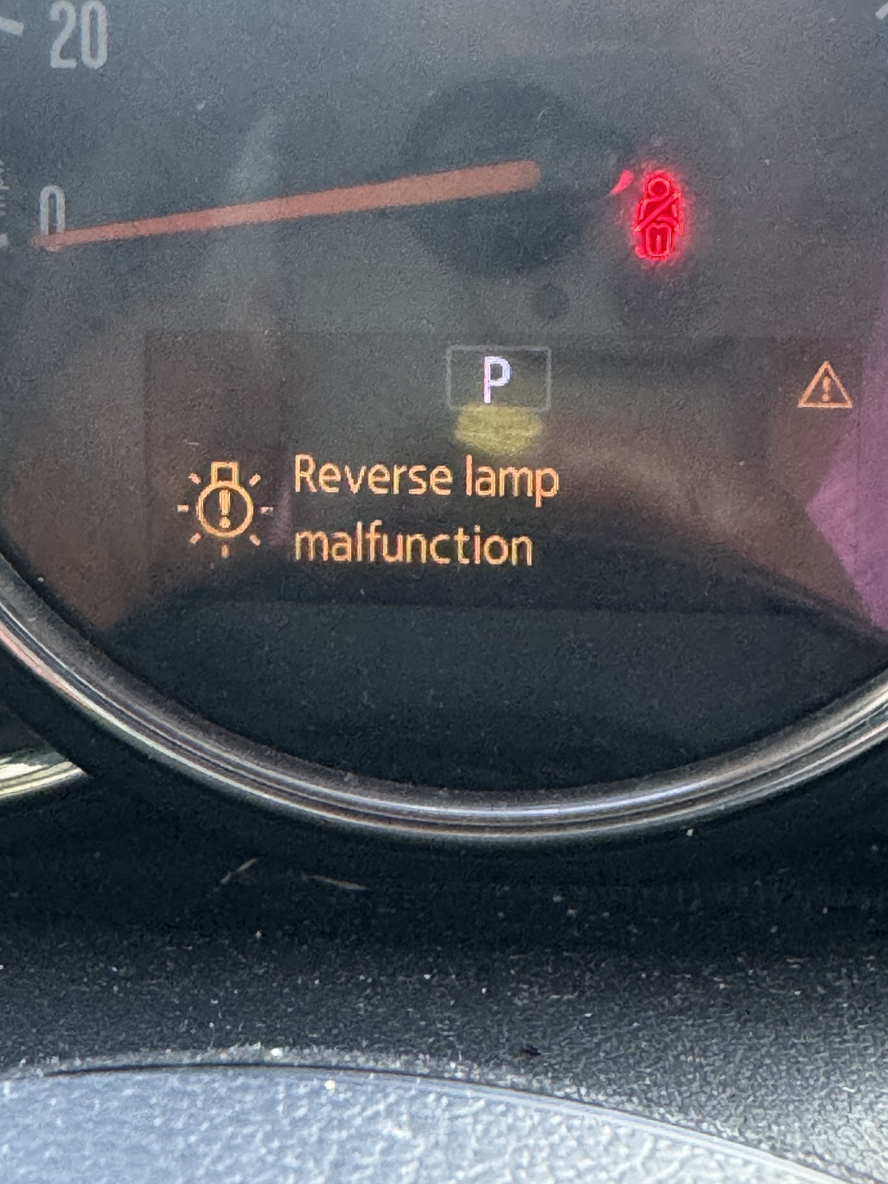
- Customer complaint Complaint Passenger-side rear light was not functioning correctly, with a reverse-lamp malfunction warning displayed in the instrument cluster.
- Inspection Diagnosis Passenger rear lamp assembly, bulbs, connector, terminals and circuit board inspected. Heat and melting damage found at the harness-to-lamp connection and its mating circuit-board terminal area.
- Diagnosis Diagnosis Damage was consistent with a high-resistance terminal connection. The exact initiating condition - bent, loose, partially seated or otherwise poor contact - could not be conclusively established after the heat damage occurred.
- Repair Repair Damaged rear light electrical connector and circuit board replaced, with the affected wiring inspected and the replacement terminals checked for alignment, seating and contact.
- Verification Verification Individual exterior-light outputs activated with a diagnostic scanner. Repaired rear lighting functions responded normally and lighting faults were rechecked.
Customer Complaint
The customer reported that the passenger-side rear light was not working correctly. The instrument cluster also displayed a reverse-lamp malfunction warning.
A rear light complaint can begin with a failed bulb, but the warning does not identify whether the actual fault is the bulb, its contact, the bulb carrier, the vehicle connector or the wiring. The complete lamp connection therefore had to be inspected before choosing a part.
Symptoms
- Passenger-side rear light not functioning correctly
- Reverse-lamp malfunction warning displayed in the instrument cluster
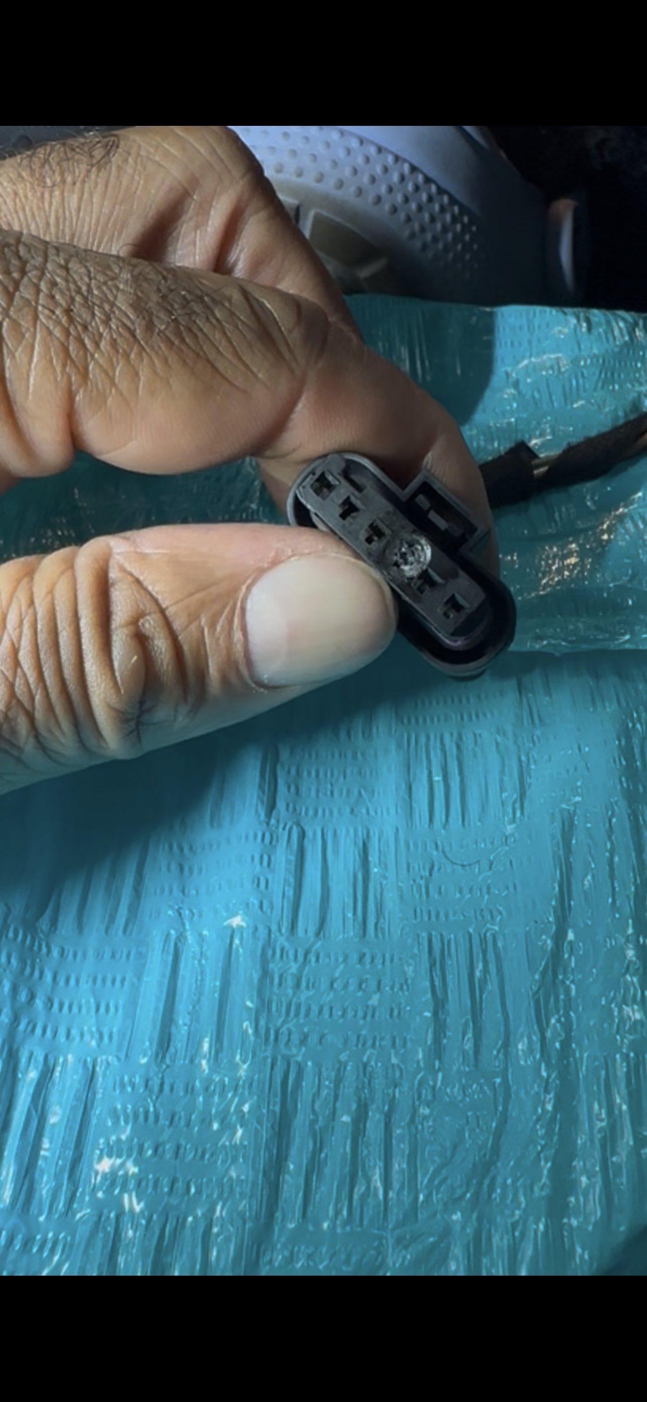
- Visible melting and heat damage inside the harness connector
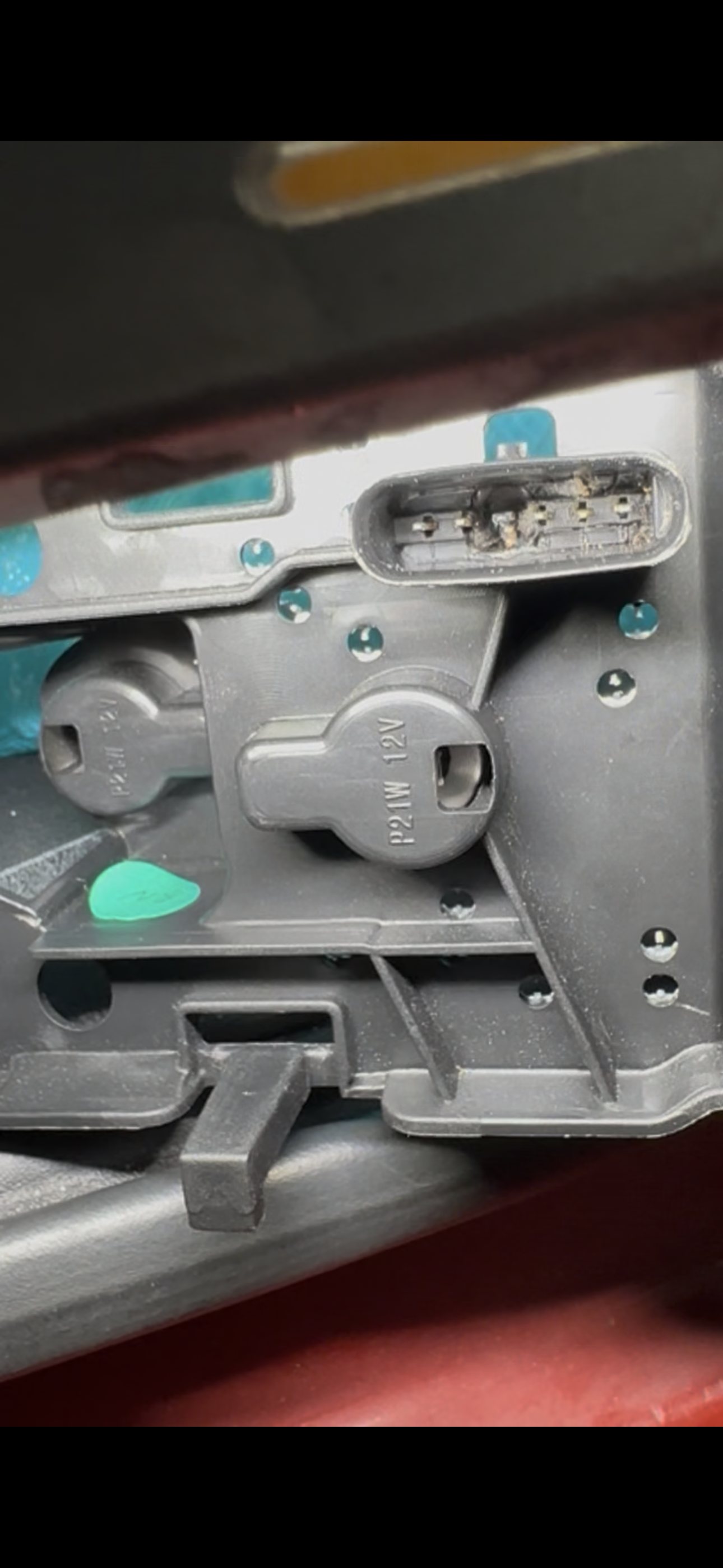
- Heat damage at the mating terminal area of the rear light circuit board
Diagnostic Process
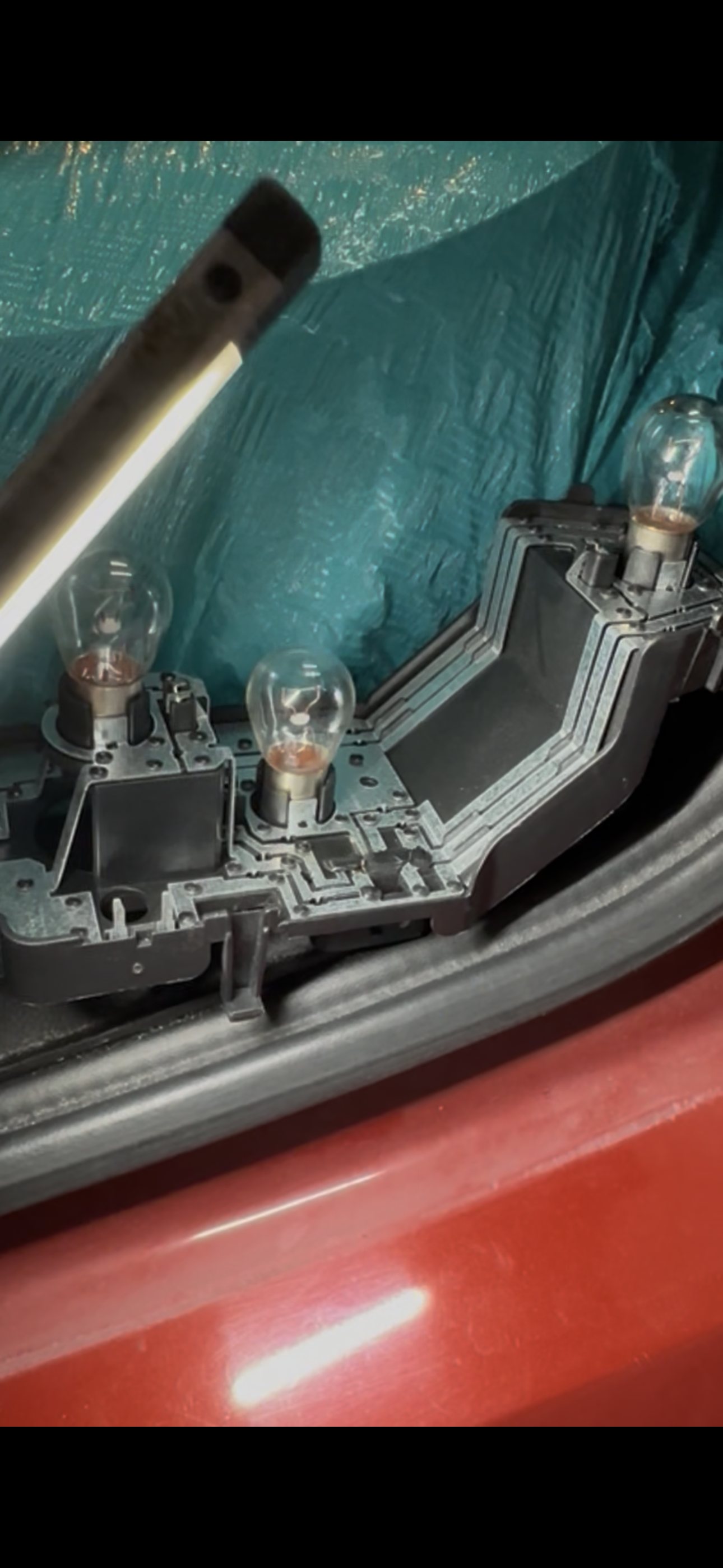
Confirm the warning, then inspect the whole current path. The warning established which area needed attention, but it did not make the bulb the diagnosis. The passenger rear lamp was accessed so the bulbs, bulb contacts, circuit board, vehicle connector, terminals and nearby wiring could be examined together.
The connector showed the decisive evidence. One terminal cavity in the vehicle-side connector was visibly melted and discoloured. The corresponding connection on the rear light circuit board also showed concentrated heat damage. That paired damage ruled out a simple burned-out bulb as the complete explanation.
Separate the confirmed failure from the initiating condition. The confirmed finding was a high-resistance connection at the connector-to-board interface. Once that area has overheated and deformed, it is not possible to reconstruct with certainty whether the terminal began bent, loose, partially backed out, incompletely seated or simply making poor contact. The evidence supports those possibilities; it does not prove which one happened first.
Understand why a connection can fail while still touching. A terminal does not have to be fully disconnected to stop being safe. Reduced contact area raises resistance, and current through that resistance produces concentrated heat:
Bent, loose or poorly seated terminal
                ↓
Reduced electrical contact area
                ↓
Higher resistance at the connection
                ↓
Connector heats while the lamp operates
                ↓
Plastic housing deforms and melts
                ↓
Contact becomes still worse
                ↓
Rear light circuit board is damaged
                ↓
Lamp function fails
The useful relationship is P = I²R: heat rises with resistance, and current magnifies the
effect. In customer terms, a connector can work intermittently or partially while quietly
heating itself enough to damage both halves of the connection.
Do not put a new part against a damaged mating surface. The connector and circuit board had to be treated as one failed interface. A new circuit board attached to the overheated connector, or a new connector attached to the damaged board, could immediately inherit poor terminal contact and repeat the failure.
Repair Performed
- Accessed the passenger rear light assembly
- Inspected the bulbs, bulb contacts, circuit board, connector, terminals and nearby wiring
- Removed the heat-damaged vehicle-side electrical connector
- Replaced the damaged rear light circuit board
- Replaced the damaged electrical connector
- Inspected the affected wiring for evidence of heat damage
- Checked that the replacement terminals were straight, aligned, fully seated and locked
- Confirmed that the connector engaged fully without being forced or placing strain on the harness
- Reassembled the passenger rear light
Parts Used
- Rear Light Circuit Board Replacement
- Rear Light Electrical Connector Replacement
Verification
The diagnostic scanner's bi-directional controls were used to command the exterior light outputs individually rather than relying only on the driver's switches.
Diagnostic scanner
        ↓
Vehicle lighting electronics
        ↓
Command selected lamp on
        ↓
Wiring and repaired connector
        ↓
Rear light circuit board and bulb
        ↓
Confirm visible operation
This is a controlled functional verification step, not a substitute for inspecting the repair. The passenger rear light functions responded normally when commanded, the connector remained properly seated, and lighting faults were rechecked after operation.
Technician Notes
The visible circuit-board damage was a consequence and a clue, not permission to replace the board and stop. The heat was concentrated exactly where the vehicle harness and lamp assembly meet. When both mating sides show damage at the same terminal, the connection itself has to be repaired as a pair.
The uncertainty about the first physical defect matters. After enough heat to melt a connector, a loose terminal can look bent, a bent terminal can lose tension, and a partially seated terminal can deform its cavity. Calling one of those the proven cause would add certainty the evidence no longer contains. The defensible diagnosis is a high-resistance terminal connection consistent with those conditions.
Scanner activation made the final check repeatable. Each available light function could be commanded while watching the repaired assembly, without coordinating pedals, gear selection and switch positions. That proved the repaired lamp responded under vehicle control; the visual inspection and fault recheck completed the verification.
The customer prevention advice is simple: never force a rear lamp connector. Pins should be straight, terminals should remain locked in their cavities, and the housing should click fully into place. A connection that still makes the lamp glow is not necessarily a healthy connection if it is loose enough to generate heat.
Lessons Learned
- A bulb-out or lamp-malfunction warning identifies a circuit to inspect, not a part to replace.
- Inspect both sides of an electrical connection whenever either side shows heat damage.
- A terminal can conduct current and still have enough resistance to melt its connector.
- Concentrated melting at one terminal is evidence of a connection problem, even when the exact original terminal position can no longer be reconstructed.
- Do not connect a replacement circuit board to an overheated connector; the damaged mating part can overheat the new component.
- Check the wire and insulation behind a melted terminal. Heat damage can extend farther into the harness than the connector face shows.
- Move one circuit at a time during connector replacement and verify every terminal is locked in the correct cavity before power is restored.
- If a connector does not seat normally, stop. Forcing it can bend a pin, spread a terminal or push a terminal backward out of the housing.
- Use bi-directional scanner controls when available to make exterior-light verification controlled and repeatable, then visually inspect the connector and recheck stored faults.
- After bulb or lamp access, verify every affected rear-light function before returning the car.
Final Outcome
The heat-damaged passenger rear light connector and circuit board were replaced together. The replacement terminals were checked for alignment, seating and contact before the lamp was reassembled. Scanner-controlled activation confirmed that the repaired rear lighting functions operated normally, resolving the original passenger rear light complaint and reverse-lamp malfunction warning.
Customer Feedback
No direct post-repair customer quote was documented. The customer was advised to make sure rear lamp connectors are never forced, that pins remain straight and terminals fully locked, and that any discoloration, looseness or melting should be inspected before the lights are operated again.
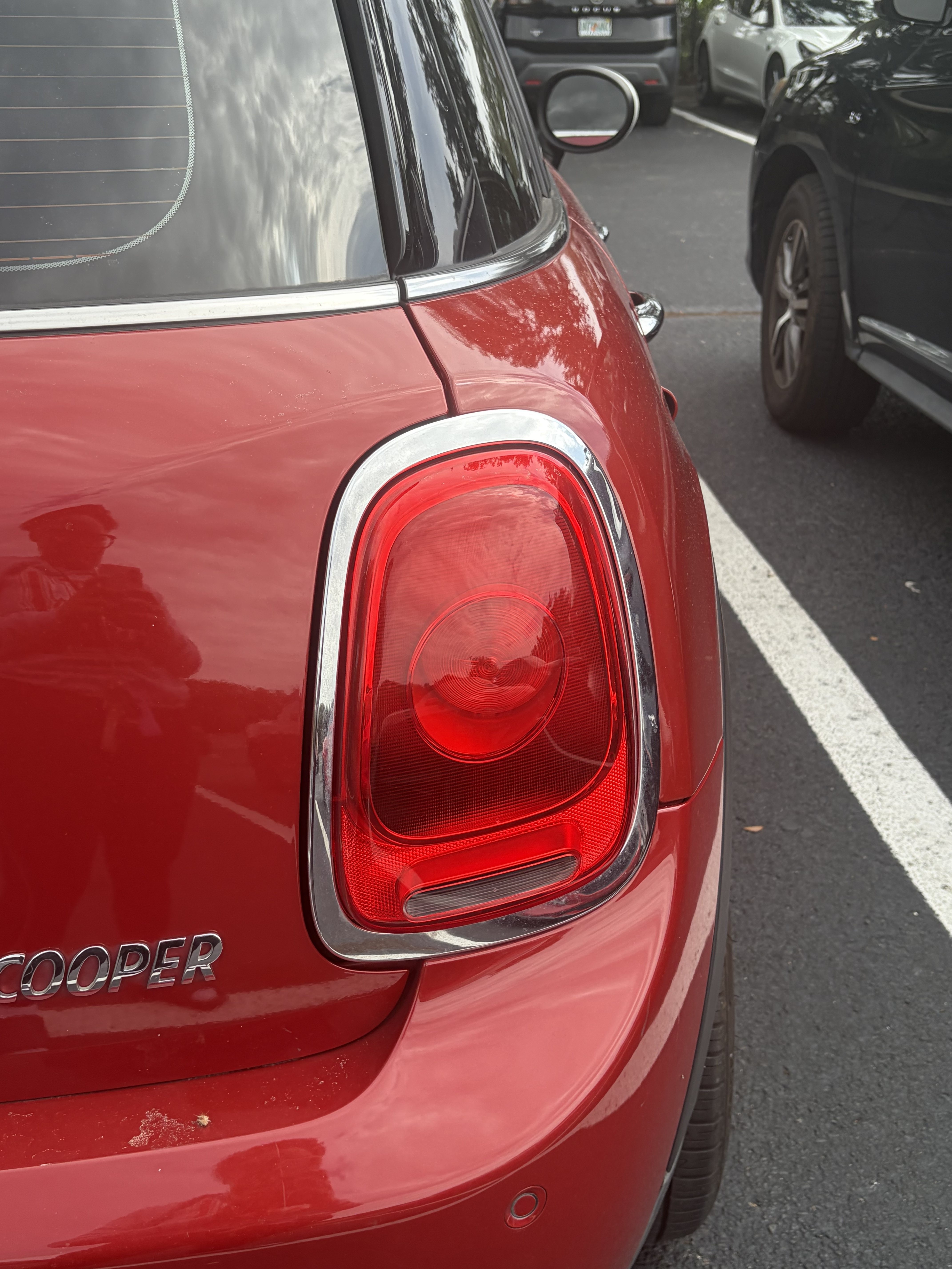
Photos From This Repair
Questions About This Repair
Why did the MINI Cooper rear light connector melt?
The damage was consistent with a high-resistance connection at one terminal. A terminal can still pass current while making poor contact; resistance concentrates heat at that small contact point until the plastic housing and mating circuit-board connection are damaged. The heat damage did not preserve enough evidence to prove whether the terminal originally became bent, loose, partially seated or poorly contacting for another reason.
Why was replacing the bulb not enough?
The failure was at the electrical connection and the rear light circuit board, not just the bulb filament. A new bulb would still have depended on the same overheated connector and damaged current path.
Why replace both the connector and the circuit board?
The two parts mate directly, and both showed heat damage. Leaving either damaged side in service could create another poor connection and overheat the replacement part.
What does scanner-controlled light activation prove?
It provides a controlled functional test by commanding individual light outputs through the vehicle electronics. It confirmed that the repaired assembly responded correctly, but it was used together with visual inspection and a fault recheck rather than treated as proof of every part of the circuit by itself.
How can this type of rear light damage be prevented?
Whenever the lamp or bulbs are accessed, inspect the pins and terminals, never force the connector, and make sure it seats and locks fully. Stop if a terminal is bent or backed out, the connector feels loose, or there is discoloration or melted plastic.
Repairs Like This One
- 11 documented Electrical repairs. See them all →
- 9 documented Diagnosis repairs. See them all →